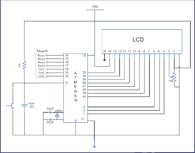
Keypad is most widely used input device to provide input from the outside world to the microcontroller. The keypad makes an application more users interactive. The concept of interfacing a keypad with the ATmega16 is similar to interfacing it with any other microcontroller. The article of Interfacing keypad with 8051 can be referred for detailed description of the methodology used here. This article explains the interfacing of a 4x3 keypad with AVR Microcontroller (ATmega16) and displaying the output on a LCD.
The algorithm and detailed explanation for keypad interfacing is given in above mentioned article. The brief steps to interface the keypad with AVR are written below:
1. Configure the row pins or column pins.
2. Make all output pins to low and input pins to high.
3. Keep monitoring the port value, where the key pad is connected.
Program related to this Project: -
// Program to get input from keypad and display it on LCD.#include _delay_us(10); if(bit_is_clear(PIND,c1)) LCD_write('1'); else if(bit_is_clear(PIND,c2)) LCD_write('2'); else if(bit_is_clear(PIND,c3)) LCD_write('3');} void check2(void){ pad=0b11111101; /pad &= (0< _delay_us(10); if(bit_is_clear(PIND,c1)) LCD_write('4'); else if(bit_is_clear(PIND,c2)) LCD_write('5'); else if(bit_is_clear(PIND,c3)) LCD_write('6');} void check3(void){ pad=0b11111011; //pad &= (0< _delay_us(10); if(bit_is_clear(PIND,c1)) LCD_write('7'); else if(bit_is_clear(PIND,c2)) LCD_write('8'); else if(bit_is_clear(PIND,c3)) LCD_write('9');} void check4(void){ pad =0b11110111; //pad &= (0< _delay_us(10); if(bit_is_clear(PIND,c1)) LCD_write('#'); else if(bit_is_clear(PIND,c2)) LCD_write('0'); else if(bit_is_clear(PIND,c3)) LCD_write('*');} void init_LCD(void){ LCD_cmd(0x38); //initializtion of 16X2 LCD in 8bit mode _delay_ms(1); LCD_cmd(0x01); //clear LCD _delay_ms(1); LCD_cmd(0x0E); //cursor ON _delay_ms(1); LCD_cmd(0x80); // ---8 go to first line and --0 is for 0th position _delay_ms(1); return;} void LCD_cmd(unsigned char cmd){ LCD_DATA=cmd; ctrl =(0< // making RS and RW as LOW and EN as HIGH _delay_ms(1); ctrl =(0< // making RS, RW , LOW and EN as LOW _delay_ms(50); return;} void LCD_write(unsigned char data){ LCD_DATA= data; ctrl = (1< // making RW as LOW and RS, EN as HIGH _delay_ms(1); ctrl = (1< // making EN and RW as LOW and RS HIGH _delay_ms(50); // give a 10 milli second delay to get thigs executed return ;} void LCD_write_string(unsigned char *str) //take address vaue of the string in pionter *str{ int i=0; while(str[i]!='\0') // loop will go on till the NULL charaters is soon in string { LCD_write(str[i]); // sending data on CD byte by byte i++; } return;} while(1) { PORTD=0xF0; //set all the input to one value=PIND; //get the PORTD value in variable “value” if(value!=0xf0) //if any key is pressed value changed { check1(); check2(); check3(); check4(); } }4. If there is any change in port value, make one of the output pin of port to zero and rest all high.
void check1(void){ //DDRD = 0xf0; pad =0b11111110; //pad &= (0< _delay_us(10); if(bit_is_clear(PIND,c1)) LCD_write('1'); else if(bit_is_clear(PIND,c2)) LCD_write('2'); else if(bit_is_clear(PIND,c3)) LCD_write('3');} 5. If any of input pin found zero, write the particular pin data to LCD, else continue with the step (4).


8 comments:
may i know the function definition of bit_is_clear() ?
It's really killing me to know whether it's library function or user defined function?
Good tutorial....helped me a lot!
Hi there, Naveen
Thanks alot for posting your code. It helped me getting my own implementation working. There are not many in-depth tutorials on this subject, and often I just see people doing all sort of bit-banging with no explanation included.
Although your code is a little too messy for my taste, I managed to get the key aspects from your code. I have used the switch -statement in my code.
Thanks!
Very nice blog...
Great information provided. We also provide AVR Microcontroller Training in Noida. I appreciate your work.
Great information...
Thanks for Sharing...
AVR Training, Embedded Systems Training, PLC and SCADA Training, Industrial Automation Training
Good Post. I like your blog. Thanks for Sharing--
Microcontroller Training in Delhi
It's very impressive to visit your site and very interesting to read all the concepts...Very Thankful for all your Effective Works...
Java training in chennai | Java training in annanagar | Java training in omr | Java training in porur | Java training in tambaram | Java training in velachery
Are you looking for AWS Training in Delhi? AP2V Academy is the best option for you! We are one of the best AWS Training provider Academy in Delhi, India. We Also conduct DevOps Training, Python Training, GCP Course, Linux Courses training, etc. Online live interactive classrooms with lifetime recording videos & 24*7 support.
Post a Comment